The present framework adopts a structured three-layer approach. These are named ITFC, HOST, and SUBMODEL. Each layer contains specific applications, each designed to serve a distinct purpose:
ITFC:Interfaces are the lowest-level applications, responsible for tasks such as sensor reading and providing input to actuators, effectively connecting to the physical layer. Ideally, ITFC apps can be developed by the owner of the hardware. The use of an ITFC layer is only necessary when data exchange towards sensors or equipment is required. Multiple ITFC apps are permitted. ITFC applications share variables through a shared variable interface (SVI), and these can be read from and written to by a HOST app.
When created within PAL, ITFC apps solely consist of user-defined time histories for predefined variables. As a result, their function is restricted to serving as tools for testing interfaces; they won’t operate live, and no connections to sensors or actuations are established. The utility of ITFC apps in PAL relies entirely on the SVI they provide, which is exchanged with the HOST layer and used for testing. This SVI must precisely replicate the one from the ITFC app developed by the hardware owner, as it is the version that will be active during live applications.
HOST:
This application operates in the middle layer and is responsible for tasks like data reading and writing to and from ITFC applications. HOST also manages variables crucial for experiment execution, monitoring, and communication between SUBMODEL applications. It generates output files in text format. Please note that as of release 1.0, each project supports only one HOST application. Data sharing is performed through a SVI, allowing read and write access by SUBMODEL apps.
SUBMODEL:
This is the top layer, comprising the primary application models, based on Simulink models. Simulink inputs and outputs are connected to an HOST SVI. Any number of SUBMODELS can be implemented within a project.
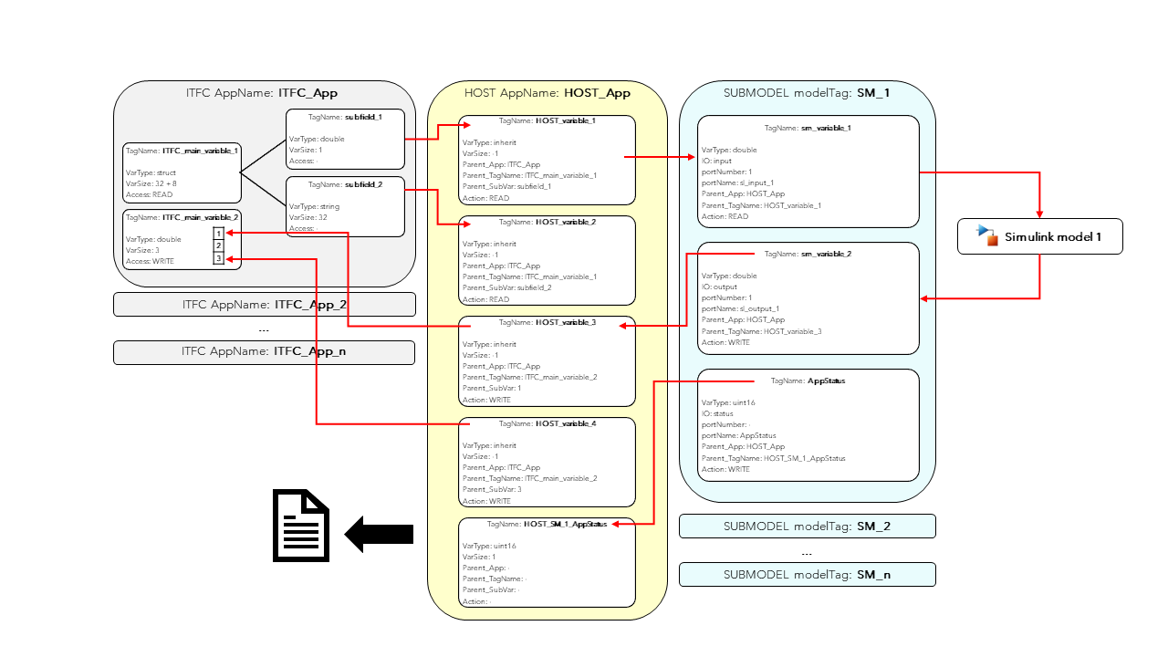
One sampling frequency must be specified for the execution of the whole framework. As of release 1.0, different frequency execution for different applications is not supported. An exemplary sketch of the framework data flow is shown in Figure 1.
Empty C source projects should be generated for each PLC application through Bachmann SolutionCenter. These source codes are then automatically modified by the framework to incorporate all the necessary variable interconnections required by the different applications.
When a new project is created using the Graphical User Interface (GUI), a folder is automatically generated with the project name. Two additional folders, ReferenceCFiles and SimulinkModels, are created to store the reference PLC source code and necessary Simulink models for the SUBMODEL apps.
Additionally, two Excel files, inputfile.xlsx and SVI_definition.xlsx are created along with the folders. These files are crucial for project definition, describing the layers of the applications architecture, and explaining how data is exchanged among each application. Both these files are described in the following paragraphs.
This file holds essential project information like folders, settings, and application layers definition. Its main tabs are detailed below.
Main Folders
In this section, users will find the necessary subfolder structure for each project, which is automatically generated upon initiating a new project. No modification by the user is usually necessary for this tab. A detailed description of each table entry is provided:
Main folder containing the dictionary for data type conversion between Matlab and the PLC. Do not change it.
ReferenceCFiles
Absolute folder path
Location of Reference C files from PLC.
SimulinkCCode
Absolute folder path
Location of Simulink Coder outputs.
SimulinkModels
Absolute folder path
Location of Simulink Models.
Settings
The “Settings” tab manages important aspects of project execution and compilation. Users must specify parameters such as sample time execution and PLC System settings. Additionally, the location of the “SVI_Definition.xlsx” file needs to be specified:
In this tab, a row is dedicated to each ITFC application. Each application can read a test interface in the form of a “.mat” file as input. The system supports the inclusion of multiple ITFC applications:
In this tab, one row is dedicated to each SUBMODEL. Each submodel must have a single Simulink model associated. There is no specific limit to the number of SUBMODEL apps permitted for each project:
This Excel file defines the data flow among different
layers in each project. It outlines the variables for each
application and defines their transmission to other applications.
In general, each application manages a shared variable
interface (SVI), which is read and written by other applications. The SVI_Definition.xlsx file comprises three
tabs, each dedicated to a layer of the framework (ITFC,
HOST, SUBMODEL). Common variable data types are detailed in the
appendix.
To promote the separation between hardware-specific and
research-specific operations, the ITFC layer should be ideally
developed by the hardware owner. Within the present framework, as already mentioned, this layer serves the unique
purpose of testing, ensuring the proper functioning of the
framework applications, primarily the Simulink submodels.
Thus, it is crucial that the SVI of ITFC applications
precisely replicates the one encountered during experimentation.
ITFC applications are “inert,” meaning they do not actively
perform reading or writing operations on any other application’s
SVI. HOST applications, on the other hand, can read and write
information to ITFC SVIs.
In addition to the mentioned data types, ITFC variables
can also be implemented as structures, where all subfields share the
same “Access” property. Numerical arrays for subfields
are not yet supported (except for string arrays). A detailed
description of all table elements is provided below.
Unique number identifying a “main ITFC variable”. Consecutive entries with same input number are considered subfields of the main structure
TagName
String
Tag name of the structure/subfield variable
VarName
String
Internal variable name in generated code. For all practical purposes, this can be set equal to TagName
AppName
String
appTag of ITFC application the variable belongs to. Not necessary for subfields. ITFC must be present in “inputfile.xlsx”
VarType
String/struct
Matlab data type of the variable. Must be included in data type conversion dictionary between Matlab and PLC. If variable is a structure, it must be set to “struct”
VarSize
Integer
If variable is a structure, VarSize should be the sum of the Bytes of its subfields. See the example for details. If variable is a subfield, only VarSize equal to 1 is allowed for numerical variables, while it can be longer for “char” variables. If variable is a main variable, any array length is supported.
Access
READ/WRITE
It must match the “Action” of the corresponding HOST variable. Set READ if the variable is read by HOST or WRITE if the variable is written by HOST
A HOST variable can READ/WRITE data to an ITFC variable, but cannot be transmitted to SUBMODEL variables.
HOST variables serve various purposes, including:
Reading variables from ITFC and host them to be read by SUBMODEL apps.
Read variable from ITFC for monitoring purposes
Creating static variables for SUBMODEL, particularly useful for constant definitions
Receiving outputs from SUBMODEL and writing it back to ITFC
Receiving SUBMODEL outputs for monitoring purposes
Receiving the AppStatus variable from SUBMODEL to assess the application’s operation
Except string variables, HOST variables VarSizeMUST be equal to 1; arrays are not allowed. When exchanging variables with an ITFC app, the Action of a HOST Variable must align with the Access of an ITFC Variable. By default, HOST applications generate three “.txt” outputs at different sampling times: fast,slow,ctrl. For each HOST variable, this behavior can be controlled by the output_freq field.
Internal variable name in generated code. For all practical purposes, this can be set equal to TagName
AppName
String
appTag of HOST application the variable belongs to. HOST must be present in “inputfile.xlsx”
VarType
String
Matlab data type of the variable. Must be included in data type conversion dictionary between Matlab and PLC. If the variable is exchanged with an ITFC app, VarType can be inherited by setting VarType value as “inherit”
VarSize
Integer
Size of the variable. Set “-1” in combination with “VarType” equal to “inherit” to retrieve the size from the ITFC app. Numeric variables must have “VarSize” equal to 1. Strings can have any VarSize
Create
TRUE/FALSE
When set to FALSE, the variable is ignored
parent_App
String
“AppName” of the parent ITFC app, if the variable is exchanged with a ITFC app. In such case “Action” must be set. It can be left blank otherwise
parent_TagName
String
“TagName” of the main parent ITFC variable. Necessary only if the variable is exchanged with a ITFC app. If the ITFC variable belongs to a structure, “parent_TagName” is the “TagName” of the ITFC structure. If the ITFC variable is not a structure “parent_TagName” is the “TagName” of the ITFC variable
parent_SubVar
String/Integer
“TagName” of the parent ITFC variable, if the variable is exchanged with a ITFC app. If ITFC variable belongs to a structure, “parent_SubVar” is the “TagName” of the subvariable. If the ITFC variable is an array, it corresponds to the index to read (1-based numbering)
Action
READ/WRITE/-
It must match the “Access” of the corresponding ITFC variable. Set READ if the variable is read by HOST or WRITE if the variable should be written back into the ITFC variable
Flag_Assign_InitialValue
TRUE/FALSE
Set to TRUE to assign an initial value to the variable. Only numerical values are supported.
Initial_Value
double
Initial value of the variable
Units
String
Units of measure of variable to be written in output file
Print_output
TRUE/FALSE
If set to TRUE, the variable will be written to the output files
output_freq
fast/slow/ctrl
Frequency at which the variable should be written to the output file
SUBMODEL variables can perform READ/WRITE operations to a HOST variable, but not on other SUBMODEL apps. For each Simulink model, it is recommended to include all model inputs and outputs as SUBMODEL variables (with the correct port numbering). Additionally, for each SUBMODEL app, include an AppStatus status variable, which informs the HOST application about whether the SUBMODEL is running.
SUBMODEL variables must be single numerical values; arrays are not allowed. The IO type field must match the type of the Simulink model port, except for “status” variables. Generally, each SUBMODEL will contain nI + nO + 1 variables, where nI/nO indicates the number of input/output ports of a Simulink model.
Variable block type in Simulink model. A single status variable must be present for each SUBMODEL, in which case “IO” should be set to “status”
PortNumber
Integer
Port numbering of Simulink model. Status variables are not numbered. WARNING: different numberings for input and output!
PortName
String
Port name in Simulink model
Create
TRUE/FALSE
Same as HOST
VarType
String
Similar to HOST, but “inherit” is not supported
parent_App
String
“AppName” of the parent HOST app, if the variable is exchanged with a HOST app. In such case “Action” must be set. It can be left blank otherwise
parent_TagName
String
“TagName” of parent HOST variable, if the variable is exchanged with a HOST app
Action
READ/WRITE/-
Action to perform on each variable. Normally, Simulink inputs are “read” and outputs are “write”
Below in Figure 2, an illustrative sketch exemplifies the data transmission involving two ITFC variables (a structure and an array). These variables are exchanged with a Simulink model.
Figure 2 Example of data transmission among ITFC, HOST, and SUBMODEL layers
To start a new session, launch the App Designer file “main.mlapp” and run it. A new GUI
will open, featuring two primary tabs which focus on distinct operations within the framework: the
Develop/Deploy and the Test tab.
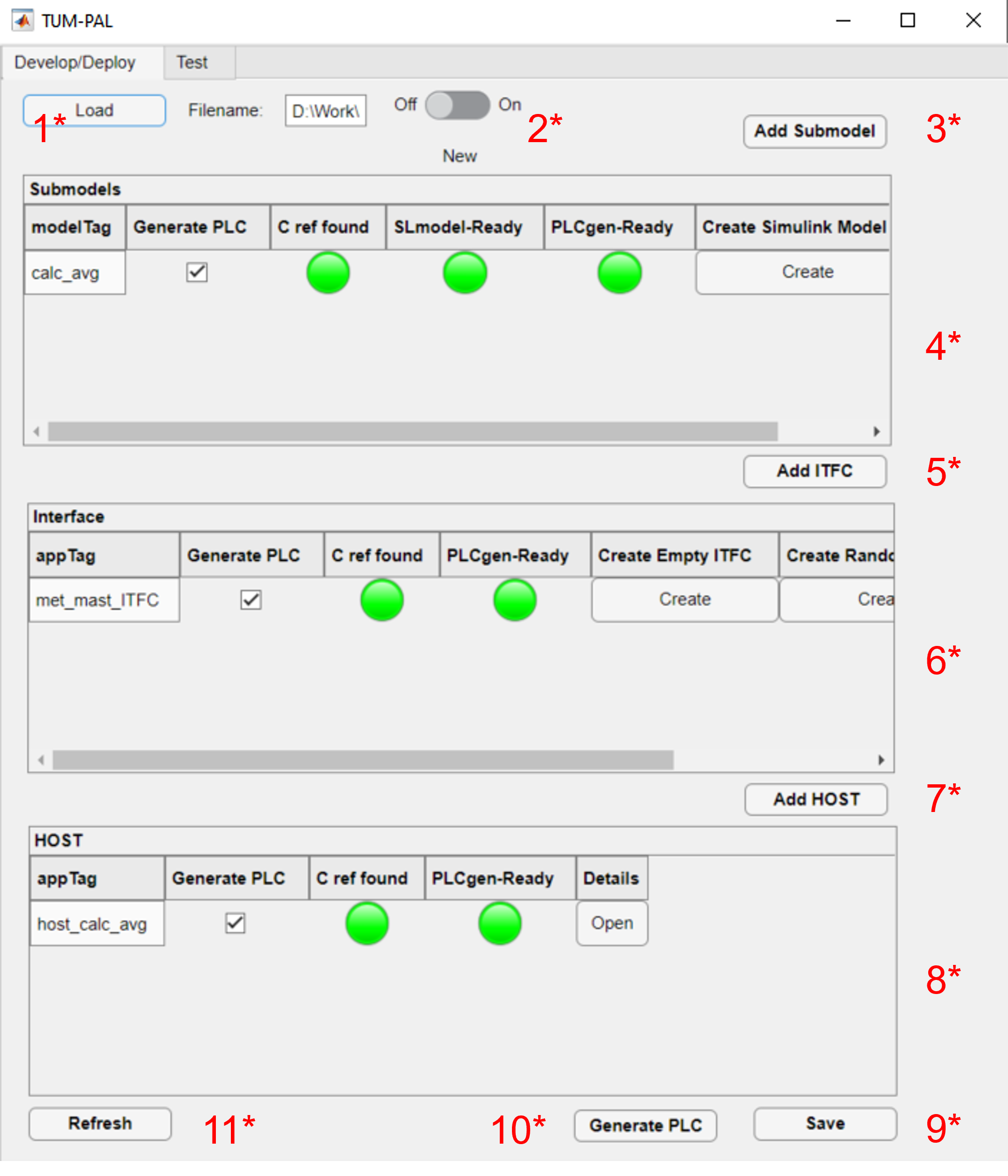
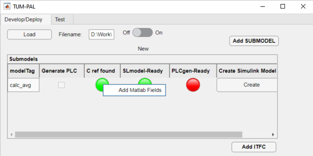
The Develop/Deploy tab allows the definition of the applications for each layer. A sample
of the GUI for the sample project “met_mast_reader” is illustrated in Figure 3.
Checkbox used to set whether to generate PLC code of Simulink mode. Linked to “Flag_Generate_PLC_app” in “inputfile.xlsx”
C ref found
This light turns green if the reference source code file is found in the folder “ReferenceCFiles\originals”. Additional fields MUST be added before code generation by right-clicking and selecting “Add Matlab Fields”
SLmodel-Ready
This light turns turn green if a Simulink model with the designated name is found in the folder “SimulinkModels” folder
PLCgen-Ready
This light indicates whether the App is ready for code generation. WARNING: remember to “Add Matlab Fields”!
Create Simulink Model
Create a new empty Simulink model. This action generates, alongside an empty Simulink model, an
initialization .m file, which can be used for configuring specific model parameters
Details
Open a tab to modify the SUBMODEL parameters of “inputfile.xlsx”
If a user intends to use an externally developed Simulink model, it is advisable to copy-paste its content into a newly created one. This ensures the retention of the Simulink model settings defined via the “Create Simulink Model” button. This action generates, alongside an empty Simulink model, an
initialization .m file, which can be used for configuring specific model parameters.
Generate an empty test interface according to the specifics defined in the “SVI_Definition.xlsx”. All numeric values will be set to 0. Filename is set as “test_ITFC_filename” of the “inputfile.xlsx”
Create Random ITFC
Generate an random test interface according to the specifics defined in the “SVI_Definition.xlsx”. Preferred option for testing. Filename is set as “test_ITFC_filename” of the “inputfile.xlsx”
Load ITFC
Load the filename “test_ITFC_filename” of the “inputfile.xlsx”
After the generation of PLC applications, the framework can be executed on the PLC hardware. The HOST
application generates “.txt” outputs, which can be used through the Test tab to verify the correctness of the data transmission between the different applications. The tab provides tools for reading HOST outputs and comparing results between PLC and Simulink, among other functions. It is important to mention that, since applications must be loaded onto the PLC sequentially, from lower to higher layers (ITFC, HOST, and then SUBMODEL), a residual delay exists between
test ITFC data and HOST data, which is of course not physical but purely introduced by this delay.
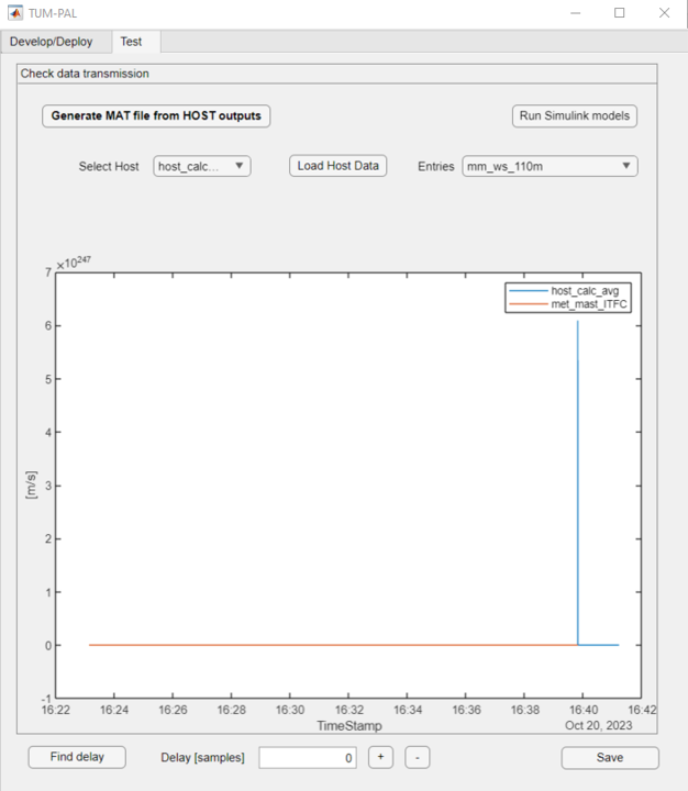
An example of the GUI for the example project “met_mast_reader” is shown in Figure 4.
Aggregate HOST output files. Select all HOST “.txt” files to convert them to a unique “.mat” file
2
Run Simulink models
Run the Simulink models with the HOST inputs currently loaded. WARNING: trim unphysical data before use!
3
Select HOST
Select the HOST app to Test. Currently only one HOST app is supported for each project
4
Load HOST Data
Load MAT file generate by the button “Generate MAT file from HOST outputs”
5
Select HOST entry
Select HOST entry to plot. ITFC and SUBMODEL curves will be added, if present
6
Comparison plot
Axes on which the variables are displayed
7
Find delay
Run cross correlation to identify delay between HOST and ITFC
8
Adjust delay
Manually specify or adjust the delay between HOST and ITFC
9
Save
Save current framework as “.mat” file
10
Brush data
Select data to keep after syncronization. See the example for details
Before running Simulink models, unphysical data should be trimmed using the Brush function, along with the “Brush Data/sync ITFC app” (right-click on the figure). Users should familiarize themselves with the testing functionality by following the examples provided.
The following subsections describe two examples derived
from wind energy applications: a Met-Mast data reader,
which can be used to read data from a met-mast and
perform moving averages for monitoring purposes, and a
SCADA-data reader.
In this first example, the user creates a simple framework to read
data from a Met-Mast ITFC app, calculate moving averages,
and determine additional inflow quantities, which are then
written back to the ITFC.
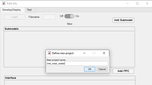
To begin, open the framework by double-clicking on the file “main.mlapp” to open the main GUI. Two options are available: loading an existing file or creating a new one. Click on “new.” Specify the folder for your new project. Open the “Examples” folder and click OK.
Specify the new project name. Call it “met_mast_reader” and click OK (Figure 5). This will create a set of subfolders, as explained in Project Definition.
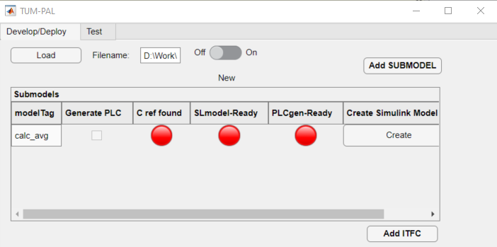
To begin, create a SUBMODEL by selecting “Add SUBMODEL” and providing a name, such as calc_avg. Click OK. The underlying Simulink model will process inputs from wind speed and wind direction data to calculate averages based on the desired window size. A new model will appear in the relative panel first row with several red indicator lights (Figure 6).
Generate an empty Simulink model by clicking “Create” in the “Create Simulink Model” column. This action creates the Simulink model in the model folder along with an “init_MODELTAG.m” file, which can be used for initializing data and constants. A green light under “SLmodel-Ready” indicates the model’s presence in the Matlab path.
Create a new Bachman Empty project within SolutionCenter, following the steps in the Create Bachmann Applications section. Call the application calavg. Ensure the main application source file is copied into the reference C folder, located in “ProjectName\ReferenceCfiles\Originals.” If the source file name, without the appendix “_app.c” is different than the project name, update it by clicking “Details” and changing the field refC_name to the new name (e.g., calavg in the present case). A green “C ref found” light indicates the presence of the reference C file in the Matlab’s path.
Right-click on the “C ref found” light and select “Add Matlab Fields” (Figure 7). This modifies the reference files, enabling the interconnection of variables.
Figure 7 Add Matlab Fields for the SUBMODEL “calc_avg”
Create the Simulink model in the appropriate folder. You can either modify the empty one, copy and paste into the existing model, or use the example provided under “Examples\met_mast_reader_sample\SimulinkModels\calc_avg.” If you plan to use a custom Simulink model, note that some model settings may differ, so it is advisable to copy the content of your model into the newly created one, as previously mentioned.
Open the model provided. The model has three main inputs:
Met mast wind speed at 110m
Met mast wind speed at 60m
Met mast wind direction at 110m
The reference heights in this example are based on the IEA Task 37 reference wind turbine. The model checks if variables are correctly being transmitted (e.g., ensuring the signals are not frozen) and then calculates moving averages. Several outputs are computed:
Moving average of the wind speed at 110m
Turbulence intensity calculated from the wind speed at 110m
Moving average of the wind speed at 60m
Power-law shear exponent
Moving average of the wind direction at 110m
Status check to monitor runtime activity
The model requires specific quantities to be defined, which can be found in the file “init_calc_avg.m” file
Quantities like startup time, moving average interval, and error time are here set to 600 s
With these settings in place, the Simulink model is ready to use
Click on the “Add ITFC” button, and in the dialog box that appears, assign the name “met_mast_ITFC” to the ITFC app.
Similarly to the steps taken for the “calc_avg” SUBMODEL, you will need to generate a new empty PLC code. Refer to the Create Bachmann Applications section for detailed guidance. Within SolutionCenter, name this application “mmitfc.” Copy and paste the reference app file into the “Originals” folder and update the “refC_name” to the new name through “Details”.
Right-click on the “C ref found” light and select “Add Matlab Fields” (Figure 7).
Click on the “Add HOST” button. Assign “host_calc_avg,” to your new host application AppName.
Complete all the required fields by clicking the “Details” button. Detailed guidance on these fields is provided in the inputfile definition section.
Similarly to the previous steps, generate a new empty PLC code for the host application following the instructions in the Create Bachmann Applications section. Name this source application hcalc.
Copy and paste the reference app file into the “Originals” folder, updating the details of the app accordingly. Right-click on the C ref found light, and from the menu that appears, select “Add Matlab Fields.”.
Set the out_filename field in the “Details” section as hcalc_outputs and provide the output_path_in_PLC (note that this will be dependent on your PLC folder path). Ensure that the corresponding folder is pre-created on the PLC to prevent potential issues during framework startup.
The basic applications – SUBMODEL, ITFC, and HOST – have been successfully created. Save your progress by clicking the “Save” button below, which updates the excel file “inputfile.xlsx.”
Open the “inputfile.xlsx” to configure the main settings for the met_mast_reader project. Changes made to the Submodels, ITFC, and HOST tabs will be reflected in the GUI upon the next project load.
Click on the Settings tab. Adjust the sample_time parameter to your desired value. Here, 0.1 seconds is chosen. This parameter determines the operating frequency for all the project applications. Note that only Bachmann systems can be selected in the PLC_system column.
Navigate to the Submodels tab. In the “host_apptag” column for “calc_avg”, specify “host_calc_avg”. This designates the host application with which the SUBMODEL application exchanges data. As mentioned earlier, it is crucial to use the same host application for every SUBMODEL. Save your changes and close the file.
Below, an overview of the different tabs in “inputfile.xlsx” for the “met_mast_reader” project.
In this step, you will define the variables for each application and establish the necessary variable interconnections across different layers. Open “SVI definition.xlsx”. A separate description is given for each respective layer.
ITFC
As a first step, it is necessary to create a dummy interface. For the current met-mast case, define two variables in the “ITFC”:
Create a structure named “met_mast”. Set both TagName and VarName to “met_mast.” Set InputNumber to 1, ensuring AppName matches the HOST app in “inputfile.xlsx.” Specify VarType as “struct,” type “READ” in the Access field, and set Create to true. Note that structures can handle variables of different data types, but their size should be 1 for all numeric variables. You can leave the VarSize field empty for now.
Define three subvariables under “met_mast”:
Wind Speed at 110 m, named “ws_110m”
Wind Speed at 60 m, named “ws_60m”
Wind Direction at 110 m, named “wd_110m”
For each subvariable, ensure InputNumber matches that of the structure, leave AppName empty, set VarType as “double,” VarSize to 1, and mark Create as true. The Access field can be left empty since it will be inherited from the structure variable.
Create a variable named “exchange_data_mm” to store and write output values from the HOST to the ITFC. Set InputNumber to 2, VarType to double, VarSize to 5, and Access to “WRITE”.
The resulting sheet can be viewed in the following table.
The “host_calc_avg” app is equipped with 10 variables:
Create three variables corresponding to the inputs of your Simulink model. These variables, being read from the interface structure, necessitate defining parent_App,*parent_TagName*, and parent_SubVar. Set Action to “READ” and output_freq as “fast” for these input variables.
Specify the outputs of the Simulink model, which comprises six variables. Among these, five are exchanged with the interface. Therefore, provide information in the parent_App, parent_TagName, and parent_SubVar fields for these. The last variable, “avg_inflow State, will not be written back to the interface. For the averaged quantities, set output_freq as “slow,” while for the “avg_inflowState,” can be printed at “ctrl” frequency.
Include a mandatory “AppStatus” variable for each submodel in the framework. As there is a single submodel named “calc_avg” in this example, add the variable “avg_inflow_AppStatus.” The type of this quantity can be a 16-bit unsigned integer. Output this variable at “ctrl” frequency.
The resulting sheet can be viewed in the following table.
The SUBMODEL “calc_avg” must be defined, according to the input port of the underlying Simulink model and its application status.
Define three variables, corresponding to the inputs of the Simulink model. Set IO as “input.” Specify the fields parent_App and parent_TagName. Ensure that the Action is set as “READ.”
Define six variables corresponding to the outputs of the Simulink model. Set IO as “output.” Specify the fields parent_App and parent_TagName. Ensure that the Action is set as “WRITE.”
Correctly define the PortNumber for both input and output variables based on the port numbering of the Simulink model. Additionally, ensure that the PortName matches the names in the Simulink model.
Create an “AppStatus” variable, denoted by the IO field set as “status.” This variable does not require a port number. The port name should be set as “AppStatus.” Set this variable to “WRITE.”
Remember to save and close the “SVI_Definition” file after making these modifications.
After modifying the “SVI_Definition.xlsx,” the project requires reloading. An error will now occur, indicating:
ITFC App “met_mast_ITFC” - variable “met_mast” is a struct of size NaN Bytes, but its subvariables sum up to 24. Please check the excel file.
This error results from leaving the “VarSize” field of the ITFC variable “met_mast” empty. To resolve this, insert 24 in the field (3 doubles of 8 bytes each).
Now, proceed with creating a dummy interface:
Open the details of the ITFC app “met_mast_ITFC” and fill in the “test_ITFC_filename” for your ITFC app, including any relative path. Create this file in “./Examples/met_mast_reader/mm_ITFC.mat.”
Click on the “Create Random ITFC” button. Specify the duration of the time histories; the default is 100 seconds. Keep in mind storage considerations on your PLC. If the duration is too long, it might pose storage issues on your PLC. However, in this case, since we have only a few variables, it should not be a problem. Set it to 1000 seconds and click “OK.”
A new “mm_ITFC.mat” file is generated. If you open it, you will find the “met_mast” structure and the “exchange_data_mm” array. Initially, these variables are populated with random data based on their data type. However, this might not be realistic for wind speed and direction data. You have two options: replace the random data with your own or use the provided dummy variables included within the folder “Examples\met_mast_reader_sample”, which contains with realistic data. By default, only the “read” variables are filled with random numbers, while “WRITE” variables are set to 0.
Open the details of your ITFC_App and set its Flag_Create_test_ITFC to TRUE. Click on “Load ITFC.”
To generate the PLC code, make sure all “Generate PLC” checkboxes are ticked, save your project, and then click on the “Generate PLC” button at the bottom of the GUI.
As a result, three folders will be created under the directory labeled PLCApps. To complete this process, transfer the contents of each of these folders into the corresponding applications folder within your PLC path.
Now, you can run the applications on the PLC through the Bachmann SolutionCenter. It is critical to follow a specific installation order: start with the ITFC, proceed to HOST, and conclude with SUBMODEL apps.
Within the HOST applications, a variable called Flag_Record is created. Use it to control the generation of output files. Wait now for the test to complete, which will take 1000 seconds. Once done, copy the output files back to the Matlab folder of the project.
In the GUI “Test” tab, generate a “.mat” file that aggregates the HOST outputs by clicking “Generate MAT file from HOST outputs.” Select all the outputs (FAST, SLOW, and CTRL). This creates a file named “hcalc_outputs.mat.”
Choose the HOST “host_calc_avg” from the dropdown menu, and load its data through the “Load Host data” button, using the “.mat” file you just created. All the host variables will be visible in the dropdown menu.
Select a variable, such as “mm_ws_110m.” You will see two curves, one from the ITFC data and the other from the HOST application. Use the figurer to verify whether the two signals are identical. In the present case, you will see something like this:
Figure 8 Data trasmission error: excessive HOST recording time
At the end of the time history, unphysical values are provided by the “host_calc_avg” application. This anomaly occurs because, after the 1000 seconds embedded in the ITFC application, random values are transmitted to the HOST application. To rectify this, you will need to trim the unnecessary data. The “Brush Data” feature facilitates this process.
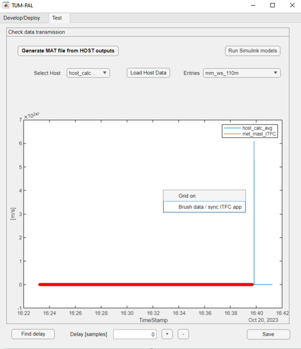
Use “Brush Data” to select the data you wish to retain.
Right-click and choose “Brush Data / Sync ITFC App.”
Figure 9 Data brushing to trim time history endings
The signals might still be affected by a time shift because the ITFC application was started earlier than the HOST application.
Figure 10 Data brushing to trim time history endings
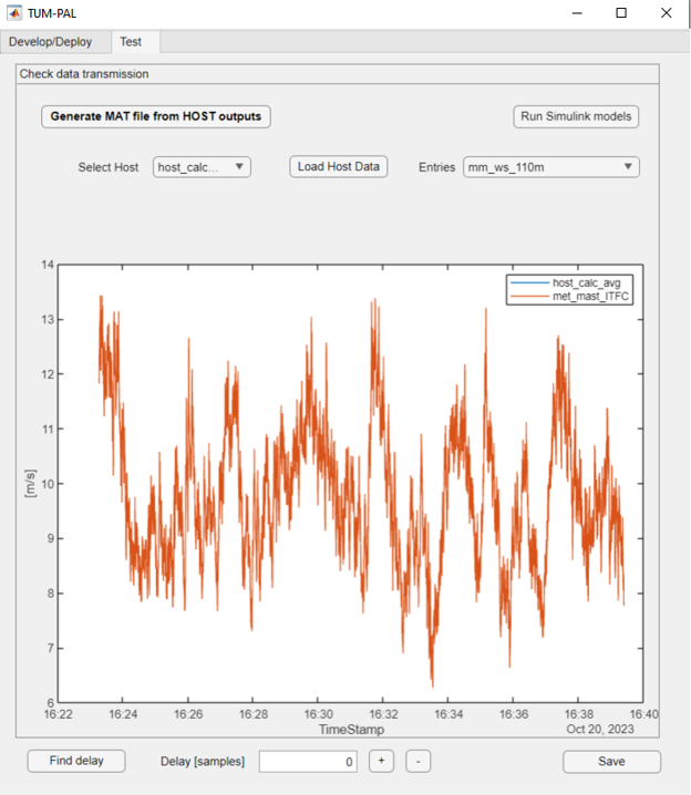
To correct this time shift, click “Find delay” and manually adjust the ITFC signal using the “+” and “-” buttons. Once synchronization is achieved, select the data to keep and use the “Brush Data / Sync ITFC App” function once more. This function will synchronize all variables originating from the same ITFC application, eliminating the need to do it individually for each HOST variables, such as “mm_ws_60m” and “mm_wd_110m.” After this synchronization, check whether the data are perfectly coincident or if there are still some transmission errors, which may be a sign of incorrect setup of the “SVI_Definition.xlsx” or some PLC errors.
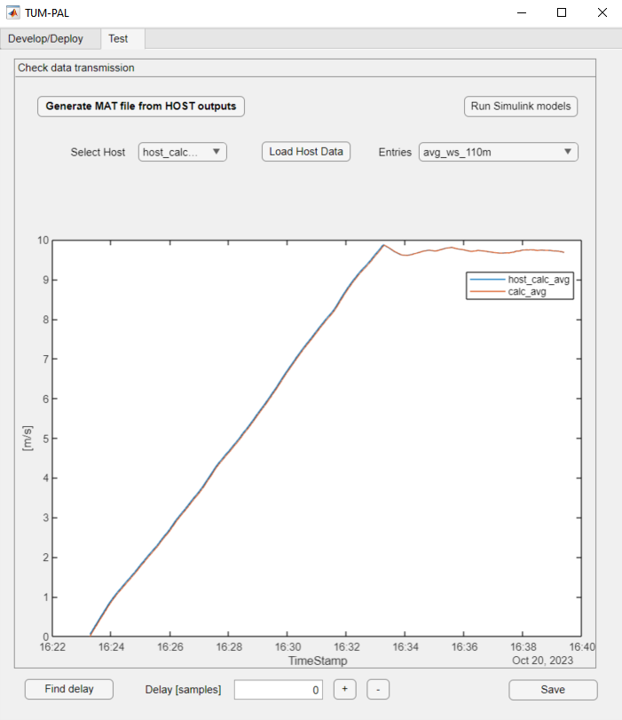
When you select “avg_ws_110m” or any variable that should be an output of a Simulink model, you might observe that only the “host_calc_avg” results are visible. To check whether the Simulink model works the same way in both the PLC and Matlab, run the Simulink model by clicking “Run Simulink models.” This uses the same inputs as the host application, allowing you to compare and ensure the C model is functioning correctly. Simulink outputs will be displayed as well.
Figure 12 PLC vs Simulink time histories for the entry “avg_ws_60m”
The comparison should align well after the initial ramp-up time required for the moving average. Verify the last two variables, “avg_inflow_AppStatus,” which should be 0 when the submodel “calc_avg” was not running and 1 otherwise, and “avg_inflowState,” which should be 0 when the submodel is running correctly and a number between 1 and 7 otherwise.
Save your results by clicking on “Save” with the desired output file name to generate a “.mat” file for future reference.
This concludes the present tutorial. Your applications are now ready for execution.
The second example in this tutorial focuses on developing a SCADA data reader for wind energy applications. It assumes that users have already followed the “Met-Mast Data Reader” tutorial, as this example will only highlight the differences between the two cases.
Begin by creating a new project and naming it “SCADA_reader.”
In this tutorial, several applications will be created:
3 SUBMODEL apps: These are connected to Simulink models responsible for inflow averaging, wind farm monitoring, and loads post-processing
avg_inflow: A SUBMODEL connected to a Simulink model performing inflow averaging
WF_status: A SUBMODEL monitoring wind farm status
loads_process: A SUBMODEL for loads post-processing
3 ITFC apps: These ITFC applications simulate data provided by different clients
itfc_scada: Simulating data from SCADA for different turbines, including rotor speed, pitch, power, vibrations, and control variables
itfc_mm: Simulating data from a meteorological mast, replicating “met_mast_ITFC” from the previous example
itfc_loads: Simulating data for blade loads on three wind turbines.
An HOST app:
host_scada: A HOST application coordinating the overall functionality and data output
The procedure to create new SUBMODEL is the same described in the previous example example (GUI):
Create three SUBMODEL, named “avg_inflow”, “WF_status”, “loads_process”
Create empty Simulink models for all the SUBMODEL apps
Create new Bachmann C projects and name them “avginflw”, “wfstatus”, “loadsprc”. Copy them into the reference C folder. Update the refC_name field using the “Details” menu
Right-click on the “C ref found” light and select “Add Matlab Fields”
Create the Simulink models. For simplicify, use the models provided under “Examples\SCADA_reader_sample”
Inspect the Simulink models; “avg_inflow” corresponds to “avg_calc” from the previous example. “WF_status” checks turbine power production and wind direction within a specified range. “loads_process” calculates out-of-plane and in-plane blade root bending moments from flapwise and edgewise bending moments.
As already done for the SUBMODEL apps, create empty PLC code and paste the reference source codes. Name it “hstscada”
Update “Details” reference C codes.
Right-click on the “C ref found” light and select “Add Matlab Fields”
Specify out_filename field in “Details” as “host_scada” and provide the output_path_in_PLC (note that this may vary on your PLC). Ensure the corresponding folder is pre-created on the PLC; otherwise, the entire framework will crash on startup
For the “SCADA_reader,” a more intricate variable mapping is required compared to the “met_mast_reader.” Each layer, including ITFC, HOST, and SUBMODEL, is detailed in the following sections.
ITFC
The ITFC applications simulate a realistic scenario with data coming from various hardware and applications in a three-wind-turbine wind farm. Each ITFC application includes the following variables:
itfc_scada contains 6 variables. SCADA data is provided through a structure variable, one for each turbine. Each structure includes subfields related to different quantities such as rotorspeed, pitch, power, and so on. In addition, vibrations are measured as well for each turbine and in the three directions, through double arrays
itfc_mm contains 1 structure. This ITFC app is identical to “met_mast_ITFC” of the “met_mast_reader” example
itfc_loads contains 1 structure, which provides data in terms of blade loads for the three wind turbines
Two additional “WRITE” variables are included within the ITFC app “itfc_scada”:
A 10-element double array used for control purposes.
A structure in which the in-plane and out-of-plane bending loads are written by the HOST.
The table below presents the list of HOST variables implemented in the “SVI_Definition.xlsx.” The variables fed to “exchange_data_ctrl” have been assigned an initial value equal to 1. Besides the greater number of variables, the data handling is similar to that of “met_mast_reader.”
After modifying the “SVI_Definition.xlsx”, the project needs to be reloaded. Similarly to the “met_mast_reader”, the correct size will need to be provided for the structure variables.
Dummy interfaces need to be generated for the different ITFC applications. Define the “test_ITFC_filename” fields for each ITFC app, named:
./Examples/SCADA_reader/itfc_scada.mat
./Examples/SCADA_reader/itfc_mm.mat
./Examples/SCADA_reader/itfc_loads.mat
Click on “Create Random ITFC”
New “.mat” files are generated for the three ITFC applications. Note that this data will not contain realistic values. You have two options:
Replace the random data with your own.
Use the provided dummy variables (located in “root\PAL\Examples\SCADA_reader_sample”) containing realistic data. By default, only the read variables will be filled with random numbers, while the others will be set to 0.
Open the details of the ITFC apps and set their “Flag_Create_test_ITFC” to TRUE. Click on “Load ITFC”.
To create e new PLC application in Bachmann, open the Bachmann SolutionCenter and follow the steps:
In the Solution Navigator: right click C/C++ projects, new, C Project.
Define a project name, which could be any name. Under Project Type, select Bachmann module -> C Template. Under Toolchains, select Bachmann 2.95 Toolchain. Next.
Insert your module name, which should be your “AppName”. Check the “SVI client for reading SVI variables”. Finish.
A new C project will be created. Under its “Source Files” folder, copy the “AppName_app.c” file into “ReferenceCFiles\Originals”. IMPORTANT: this file name, without the appendix “_app.c” is the “refC_name” to be written in “inputfile.xlsx”. This is the main application file, which needs to be modified to include the app interconnections.